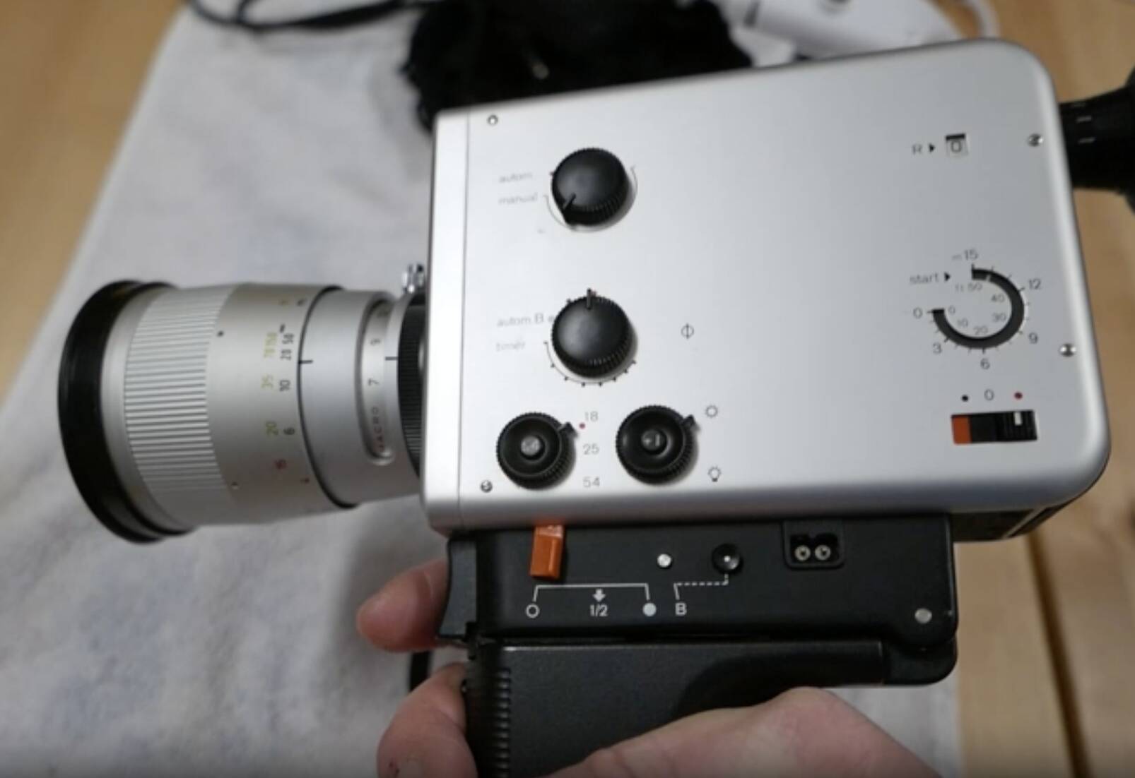
After I was able last fall to put my H8 RX in the closet as repaired, I now turned my attention to the defective Nizo Professional at the beginning of this year.
In 2022 at the Deidesheim film fair, the camera already showed the more than unpleasant behavior of lagging for some time after the shutter button was released. In the video shown, it is only up to one second, but (demonstration effect) it is sometimes five seconds or more.
The main problem is that it doesn’t generate any sync pulses during this “unsolicited keep-running” time, which already made editing the Deidesheim 2022 movie difficult for me. In addition, it takes several pictures irregularly, even in single-frame mode, which spoils any stop-motion trick.
So I followed the error description on this page:
ACWSOFT – Super 8 – Kodak Ektachrome 100D E100D, Camera, Cameras, Nizo
The article and the picture there don’t exactly encourage a DIY repair… 😞
Many (thin and short) wires connect the various circuit boards to each other and to the main housing.

But I went ahead with it anyway. Firstly, the Nizo Professional is a very good camera, secondly, I’ve grown fond of it and finally I want to make more sound films again, which is only possible with great pain, you have to add impulses to the impulse-free “ends” of the takes by ear in the audio editor.
I have various side cutters, watchmaker’s screwdrivers and a soldering iron ready, as well as the spare parts of course. And (Friedemann’s tip) a white terry cloth towel as a base to prevent small screws from bouncing away

The procedure:
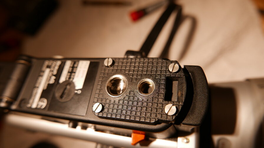
1. remove battery basket, eliminate risk of damage due to short circuits
2. unscrew the base plate

3. Unscrew the handle carrier

4. lift the handle very carefully (pins fix it to the housing) and turn it to one side (the correct side!)

5. Loosen the six small brass screws on the upper circuit board and do not (!) lose them.

6. This circuit board can now be carefully lifted upwards out of the handle. The components of this circuit board are located between the components of the circuit board below. In addition, both have thin wire connections to each other and to the main housing through a gap in the housing, so they can no longer be moved freely.

7. Now you can see the 470µF and further down (towards the main switch) another electrolytic capacitor


8. I decided to replace both electrolytic capacitors after 40 years and removed them with a special side cutter. Good light and a steady hand are important here.


9. the new components have a higher dielectric strength than the old ones, but are smaller in size

10. and after soldering to the stubs of the previous ones, when installed
(when soldering, take care not to damage any wire insulation, plastic parts or scratch the housing)


11. Now “suck/smudge” the circuit board back into the box

This was more than challenging, as it only fits in exactly one position, you can’t see anything and the tiny brass screws have to fit back into the small brass tubes that protrude from the bottom of the handle carrier and support the top circuit board

That’s it! 🙂
12. Screw everything back together (and don’t forget the release button, which is only inserted, as I did)
And then the first test:
Strangely enough, the camera did not work immediately without errors, but initially showed the old error image.
After a few attempts, however, it now works perfectly.
Now the final test of all the functions of the handle:
- All pulse outputs (I did not test the pilot tone, however) with the sound recorder and headphones
- Flash contact in single image with flash
- External power supply with the Braun power supply unit for Nizo
- Electric remote shutter release (both with the original Nizo and the one from hama)
- Mechanical remote release

A schematic for the Nizo Professional would be very helpful, also to better understand the special functions that are implemented in the handle, but I can’t find one on the net. The other silver models (S48, S560, 801macro etc.) can be found more often, but not the Professional.


Related Posts